The Electronics Newsletter appears today in the form of a small tutorial on the protection of electronics with the title The influence of the coefficient of thermal expansion on the thermal fatigue resistance of transformers and modules.
Introduction
The coefficient of thermal expansion, or thermal expansion coefficient, is a characteristic value describing the behaviour of a material in relation to dimensional changes due to changing temperatures – and is therefore often referred to as the thermal expansion coefficient. The responsible effect significantly influences the thermal fatigue resistance of transformers and modules. The temperature fatigue resistance also depends in part on the chemistry employed and on the following parameters:
- The glass transition temperature (Tg)
- The elastic modulus
- The coefficients of thermal expansion (CTE)
- The number of test cycles
- The geometry of the housing
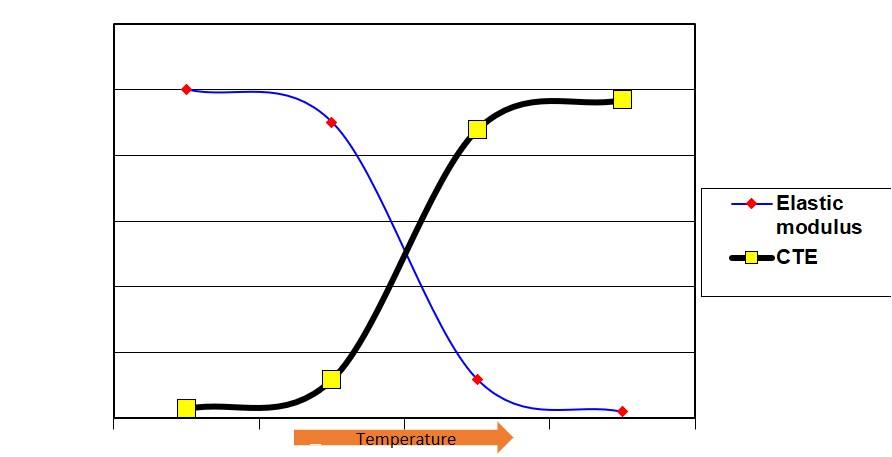
The thermal fatigue resistance depends on the glass transition temperature (Tg), the coefficient of thermal expansion (CTE), the number of test cycles, the hold time of the module geometry and the elastic. The elastic module is defined as the slope of the stress-strain diagram with single-axis loading within the linear elasticity region. This linear region is also known as the Hookean region.

Here, σ represents the mechanical stress (normal stress, not shear stress) and ε the elongation. The elongation is the ratio of the variation in length to the original length. The elastic modulus has the same units as the stress.

Since, together with the Poisson ratio, it describes the law of elasticity, the elastic modulus is considered to be a material constant, However, the elastic modulus is not constant in relation to all physical variables. It also depends on the environmental conditions, such as temperature, humidity or deformation rate.

Elasticity results in a lowShore hardness. On the other hand, a low coefficient of thermal expansion causes a high Shore hardness. These phenomena oppose each other physically. Furthermore, existing market demands require that the glass transition temperature lie outside of the operating temperature. This significantly limits the choice of material and unnecessarily increases the price. There is no indication of how to deal with this general problem
The thermal fatigue resistance depends on the geometry of the module
The low elasticity of e.g. metal housings compared with plastic housings is more likely to cause “fracturing” of the sealing compound or the module.
Changing the structure of the chip, for example from TSSOP to QFN (Quad Flat No-Lead) also has consequences. The QFN package is around 60 % smaller than the TSSOP (thin shrink small outline package). Due to their compactness, QFN housings are ideally suited for mobile data terminals. QFN packages are SMD components with terminal contacts on the lower side of the package, with which they can be directly mounted on the printed circuit, instead of wire connections. Therefore, compared e.g with TSSOP, elasticity is no longer present.
The thermal fatigue resistance also depends on the number of test cycles and the hold time
Achieving “stress-resistant“ results requires modern climatic test consoles for the simulation of climatic conditions, exact climatic test cycles and reliable monitoring of the test runs. Here, the possibility to generate program cycles, store and display test results, and evaluate the test run are prerequisites.
The temperature range should cover temperatures from –40°C to +140°C and allow changes between 2 and 5 K/min. A clear distinction must be made between:
- Temperature cycle test (changeover time to 5 K/min) and
- Temperature shock (changeover time < 30 seconds!)
| For the example of 2K polyurethane sealing materials, both a low elastic modulus, i.e. a flexible material, or limited elongation, i.e. a high elastic modulus, can influence the temperature. |
If you have any questions about material selection or specific applications, please do not hesitate to contact us directly at bectron.ELANTAS.europe@altana.com
